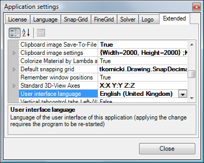
Application settings (dialog)
The (extensive) set of application settings can be accessed vie the Menu
Edit→Settings from the main menu
and adjusted within the dialog window.
 Amongst other following settings are
available:
Amongst other following settings are
available:
- language of the user interface (currently English or German)
- loading the recently edited project,
- automatic calculation of secondary functions (heat flux, relative humidity on surface etc.),
- standard directory to save project to,
- user defined logo for report headings
- etc.
Settings shown and adjusted in this window are applied to the application and are independent from project specific parameters (compared to current fine grid parameters of the project, for example, saved with the project).
Changes to some parameters require an application restart (e.g. User interface language) - if so it is emphasized in the description specific parameter.
Parameters which are composed of a set of detailed settings are shown with a plus symbol to the left of the parameter name. A click onto the plus symbol will expand the list of detailed setting offering them for editing.
The bottom part of the window displays the description of the parameter currently selected. The height of this part of the window can be adjusted by dragging the splitter bar.
Every change to the settings are applied immediately (eventually requires application restart too).
The button "Close" or ESC-Key close this window.
Evaluation |
|
| Relative Close-Up Error limit | Relative Close-Up Error maximum criteria for coupling
coefficient determination.
The value set here is used to show
precision missed marks (*) and (**) within the coupling coefficient
precision information. Remark: Further precision analysis of the calculation shall be considered if current error values are above this limit. Default: 0.0001 (defined by EN ISO 10211:2008); Range: 10-10 to 1.0 |
| Relative Close-Up Error - Warn if above |
Display a warning message if precision criteria (limit
for the relative close-up error of all boundary conditions) is not
fulfilled. Default: On |
| Standard Boundary Conditions |
Default values of
boundary
conditions (temperature and relative air humidity) for the evaluation.
These values are used only during the first evaluation of a project. Following defaults are defined:
Spaces are sorted alphabetically by their name. All but first space will receive these values by default. First space will be assigned its specific values.
Remark: If the project template "projekt.xml" contains boundary conditions already, that will have the priority over the values specified here. |
| fRsi,min design factor for condensation assessment | Minimum value fRsi,min of the temperature factor of interior surfaces for the condensation-free
assessment (within
results report). Undercutting this value should mean that condensation free assessment criterion of interior surfaces is not
fulfilled. Important: The value fRsi,min is dependent on interior climate (temperature, air humidity) and can be referred within local regulations. Default: 0.69, Range: 0.0-1.0 |
| fRsi,min design factor for mould-free assessment | Minimum value fRsi,min of the temperature factor of interior surfaces for the mould-growth-free assessment
(within
results report).
Undercutting this value should mean that mould growth free assessment criterion of interior surfaces is not
fulfilled. Important: The value fRsi,min is dependent on interior climate (temperature, air humidity) and can be referred within local regulations. Default: 0.71, Range: 0.0-1.0 |
| fRsi,min design factors - Warn if undercut | Display a warning message within
results report if mould- or condensation-free criteria is not fulfilled (fRsi,min design factors are
undercut). Default: On |
| fRsi - Two-Space only evaluation | Evaluate fRsi temperature factors (within
results report) only if exactly 2 spaces (temperatures) and no further
boundary conditions exist in the model. Default: Off (temperature factor are always calculated) |
| Always Expose Graphical Evaluation | The graphical evaluation window (Results
3D window) will be opened automatically each time
boundary
conditions are applied. If this setting is turned off (False) the graphical evaluation, if not opened yet, will be not initiated - computationally very intensive and memory consuming evaluation is not requested. Only the results report will be created and exposed. Default: On |
| Evaluate secondary functions | Secondary functions (like heat flux, relative
surface humidity, etc.) will be calculated for graphical evaluation. If this setting is turned off (False) only temperature field will be calculated for Results 3D evaluations. This saves significantly time needed for calculation and reduces memory demand during evaluation. Default: On |
| Evaluate which secondary functions |
Allows selective selection of secondary function to be calculated for
graphical evaluation.
Further secondary function are available with the active VAPOUR-Option:
Remark: Application settings specific to the VAPOUR-Option (partial pressure, pressure difference, interstitial core humidity, vapour flux and vector) can only be changed if the DAMPF2/3DIM license option is available (otherwise are shown as Read-Only). Remark: This setting is only meaningful if the setting "Evaluate secondary functions" is turned on. See also:
Parameter setting
"Evaluate secondary functions",
General
(control panel) |
| Restore last Result3D Parameters | Defines how (and if) to restore the
Results3D Parameters
on first display of the Results3D
window (the combination of evaluation parameters is saved when the
Results3D window is closed).
Default: RestoreAdapt (earlier versions, up to 4.80: No) |
User Interface |
|
| Autosynchronize materials & surfaces | Defines if the project specific
material list and
surface list are
automatically synchronised (on each element selection change). This can
be also change on the
context menu of both lists ("Autosynch. from Elements") See also:
Material window,
Surfaces window |
| Colorize material by Lambda automatically | Defines if the
material colour is automatically calculated and changed then the value
of Lambda changes (by
LambdaToColor-Table).
When off the colour assigned to the material will be retained during changes
to the value of Lambda. See also:
Material Editor window,
Element Editor,
Colour setting file
LambdaToColor.ColorList |
| Clipboard image settings / Clipboard image size |
Dimensions (in pixels) of images shot from 3D views and
placed onto the clipboard (via Copy Image). Please keep proportions (width/height) of the image targeted for the clipboard same to proportions of the view on the screen. If proportions differ the resulting image placed on to the clipboard will probably differ (in its scaling) from the view seen on the screen.
See also:
Keep View Aspect Ratio,
Copy image to
clipboard,
Export image to file |
| Clipboard image settings / Keep View Aspect Ratio |
If turned on (True) the proportions of the image placed on the clipboard
will reflect the proportions of the image shown on the screen. Preset
dimensions (see above) of the image will be treated as maximum values
for the resulting image (the resulting image will fit into the rectangle
given by the dimensions specified)
See also: Clipboard image size,
Copy image to
clipboard,
Export image to file |
| Clipboard image Save-To-File option | Defines if after
copying the
image onto the clipboard an option to save the image to the file (Save
Image dialog) shall be offered also. Default: Off |
| Remember window positions | Positions of windows on the screen shall be saved and
windows shall reopen at positions saved lately. Default: On |
| Background 2D colour | Background colour of 2D views (
Elements 2D,
Elements 2/3D,
...) Default: Black |
| Background 3D colour | Background colour of 3D views (
Elements 3D,
Results 3D,
...) Default: WhiteSmoke |
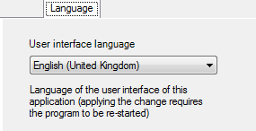
| User Interface Language | By default the user interface of the application reflects
the language of the operating system
(standard/default language). The user can change this setting!
If the language setting is not supported by the application (current distribution provides only English and German), the application will fall back to English. Be aware
of:
Country specific localisation |
| Standard 3D-View Axes | Defines titles displayed along axes within 3D view (used in
Elements 3D and
Results 3D window) Default axes titles: X, Y, Z |
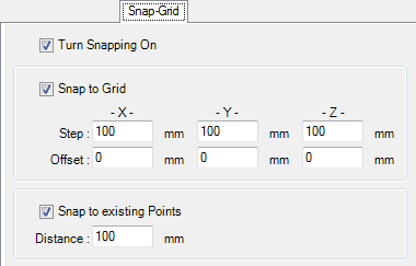
| Default snapping grid | Defines settings of Snap-To-Grid functions (used in
2D Element Editor) See also:
Snap-To-Grid
parameter |
| Vertical tabcontrol tabs Left-Alligned | Tabs of the
control panel within
Results3D window will show at the left edge of the window (instead of
the default at right side). This setting allows to change the placement of tabs to the left side of the window which might be common to architects and engineers. This reflects familiar tilt of the head to the left to read tab labels. Default: Off |
| Vertical tabcontrol tabs with Labels | Tabs of the
control panel within
Results3D window will show labelled with Text Default: On |
| Vertical tabcontrol tabs with Icons | Tabs of the
control panel within
Results3D window will show graphical symbols also. Default: On |
Project Files |
|
| MRU Project Count | The Number of recently processed project names (paths) the application shall remember. (value range 0-200,
-35 with menu shortcuts) Default: 8 |
| Reopen last project | The last project saved or opened prior to application exit
will be reopened automatically on next application start. Default: On |
| Overwrite project without asking | The project file will be overwritten without any warning or
approval (only if the name for the project file is already set). If the name of the project file is already set (either saved or loaded) saving the project is executed without any additional warnings. This simplifies the step „Results…“ – when combined with AlwaysAskForFineGridParams=FALSE and AlwaysAskForSolverParams=FALSE the application shows results directly. Default: On |
| Always Ask To Save Project | You will be reminded to save current project prior to any
destructive operations (this the default behaviour). Prior to disposing
data of current project (New,
Load,
Convert etc.) the user
will be asked to save the project. Default: On |
Projects |
|
| Create Directory For Reports | When creating a new project, create a directory where the reports and related images are stored. Default: Off |
Grid |
|
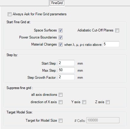
| Always ask for fine grid parameters | User will be asked to adjust and confirm fine grid
parameters (the dialog
Fine-Grid parameter
will be shown) on each computation. Default: On |
| Default fine grid parameters | Default values of
parameters used by
fine grid generator applied to new projects See also: Fine-Grid parameter |
Solver |
|
| Automatically close Solver Form | The Solver window
will close automatically when the computation is finished. If this setting is turned off (False) the application will wait until the user manually closes this window (by pressing the button "Close"). Keeping the window visible can be helpful when further detailed analysis of messages produced by the solver is required (e.g. at some error conditions). Default: On |
| Animate Progress on Solver Form | Show the progress animation on
Solver window. If this setting is turned off (False) the animation will not show thus saving CPU time. Default: On |
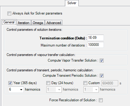
| Always ask for Solver parameter | User will be asked to adjust and confirm
Solver parameters on
each computation (the dialog
Solver parameter will
be shown). Default: On |
| Default Solver parameters | Default values of parameters used by the simulation engine
applied to new projects. See also: Solver-Parameter |
| Run Solver On Multiple Processors | Run the
Solver utilizing multiple processors or
processor
kernels. The maximum number of processors utilized is set with the parameter "Max Number Of Solver Processors". Remark: This setting can be
changed only if there are multiple processors (or processor cores) available
in the system used. Default: On (subject to license feature MULTICORE and the OS reported number of processor above 2). The user shall adjust the Number Of Solver Processors to achieve optimum performance. |
| Max Number Of Solver Processors | The Maximum Number Of Processors utilized by
Solver (if it
shall run on multiple processors).
The number entered is limited to the actual number of processors (or
processor cores) currently installed and available in the system. The user shall
adjust this number to achieve optimum performance. 0 (default) - utilize all available processors/cores. Remark: This setting can be changed only if there are multiple
processors (or processor cores) available in the system used. |
| Warn on excessive Equation Size | Display a warning message in the Solver if the equation size is above the value specified (0 - disable warning). Default: 1000000 |
Directories & Files |
|
| Material Database | Path to the
Material
database Default: <installation folder of the program>\Baustoffe.xml |
| Simulation Folder Cleanup (Reminder) | Set the number of days after the latest invocation of the
Simulation Folder Cleaner Tool to remind you about the cleanup of
intermediary simulation results eventually needed. If you ignore the
reminder when shown, the setting is raised by 1 automatically.
Default: 30 (days) |
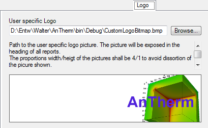
| User specific Logo | Path to the
User specific logo file.
The logo image is displayed in the heading of reports, as middle item of the heading, placed left to the Copyright-Info, 6cm wide and 1.5cm high. To avoid distortion of the picture keep the width to height ration of 4:1 (for example 800x200 pixels). If no logo image shall be shown on reports leaving this field empty is allowed. Default: <installation folder of the program>\CustomLogoBitmap.bmp |
| Default project directory | The Path to the folder to which
project files shall be
saved. This setting is only used for dialogs of save/load menus if the project currently processed has not been saved to file ever yet (this is valid for new projects). Default: "My Documents\AnTherm" |
| öbox data download folder | Path to the store of
öbox-data which then are shown
within
material database window.
Default: <LocalApplicationData>\OeBOX_Downloaded, |
| baubook(öbox) data included | Include
baubook(öbox)-data
(if available) within
material
database window. This, if turned off, allows you to exclude
baubook(öbox)-data
from the view even if the baubook(öbox) data file is available. You will have to close and reopen the material database window to fully apply change in setting of this switch. Default: On |
| BPHDB.COM data included | Include
BPHDB.COM data
(if available) within
material
database window. This, if turned off, allows you to exclude
BPHDB.COM data
from the view even if the BPHDB.COM data file is available. You will have to close and reopen the material database window to fully apply change in setting of this switch. Default: On |
Special (Advanced) settings
Settings collectively grouped here are used to adjust behaviours and techniques used by the program. Such special adjustments must be accounted also to reflect various differences in hardware used, which cannot be automatically analysed and might lead to undesirable behaviour of the application.
Advanced UI Settings |
|
| Alpha (surface transmittance) hidden | Hide the Alpha field (surface transmittance Alpha=1/Rs) within space surface property input. When turned off both reciprocal inputs of surface resistance Rs and transmittance α are offered (compatible with versions prior to 6.102) on Element Editor and Surface Editor forms and reported on Modelling Report. Default: On |
| Elements23Form Panel Contents | Contents shown within quadrants of
Elements23 window can be
adjusted and contain choices of parallel projections
XY, XZ, YX, YZ, ZX, ZY, the
3D view and
element selection
list. One can also do without showing anything within quadrant (in most
cases the 3D view might be obsolete). Default:
|
| Primary Edit Windows 2D-Project |
Defines which
Editing windows will automatically open for
2D project. Default: Description, Element Editor, Element selection, Elements 2D |
| Primary Edit Windows 3D-Project |
Defines which
Editing windows will automatically open for
3D project. Default: Description, Element Editor, Element selection, Elements 23 |
| Primary Edit Windows 3D-Layered-Project |
Defines which
Editing windows will automatically open for
layered 3D project. Default: Description, Element Editor, Element selection, Elements 2D, 3D-Layers, Elements 3D |
| Restore last Camera Position | Restore to the recent Camera position on initial display of
a 3D window (applies to
Elements3D, Elements23,
Results3D).
Default: RestoreAndFit |
| Show using Visual Styles | When enabled Buttons and other controls will render with (new) visual style, e.g. rounded. Default: On You will have to end and restart the application to consistently apply the change of this setting. Remark: For Windows XP the default is "Off" to overcome some compatibility issues resulting from implementation error on that systems when showing text on vertical tabs of the tab control which are not rendered properly if visual styles are enabled. The user can still enable that setting manually. |
| Help Window shown TopMost | Help window will be shown topmost to application windows and automatically minimize with the application
(this is the windows default behaviour). When turned off (the default) the help window can be set behind the application
window via typical desktop window manager. Remark: It applies only to Help.ShowHelp but not the HelpProvider (invoked via F1 key) thus the effective behaviour depends on how the help window was opened. If HelpProvider opens the Help window (user pressed F1 key) then the default (TopMost) behaviour will be always retained. If Help.ShowHelp opens the Help window (via Help-Contents, Tutorials, etc.) then the behaviour set here will be retained also for subsequent F1 requests. Default: Off |
Advanced Settings |
|
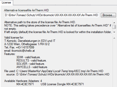
| Alternative License File AnTherm.HID | Alternative path to the store of the
license file AnTherm.HID. Important: This setting, if not empty, takes precedence over the "Alternative list of license files AnTherm.HID". If left empty (default) the license file AnTherm.HID is looked for within the installation folder, and, if not found there, within the subfolder DemoLicense of the installation folder. Important: A valid license file MUST be named AnTherm.HID. AnTherm will create a temporary local copy of the file provided to also allow network stores without additional performance penalties. ZIP Archive: specifying a ZIP archive storing the license file AnTherm.HID in its top level directory is also supported. If the file specified does not exist, this setting is simply ignored. Default: empty Important: You will have to end and restart the application to consistently apply the change of this setting. |
| Alternative List of license files AnTherm.HID | The list of alternative paths to multiple stores of
license files AnTherm.HID of which the first valid or first marked expired will be
employed. Important: The setting "Alternative license file AnTherm.HID", if not empty, takes precedence over this one (which then will be ignored). If left empty (default) the license file AnTherm.HID is looked for within the installation folder, and, if not found there, within the subfolder DemoLicense of the installation folder. Important: A valid license file MUST be named AnTherm.HID. The name of a ZIP archive storing the file AnTherm.HID can be set alternatively too. AnTherm will create a temporary local copy of the file provided to also allow network stores without additional performance penalties. If the file specified does not exist, this setting is simply ignored. Default: empty Important: You will have to end and restart the application to consistently apply the change of this setting. Remark: The purpose of this setting is, in the case you have multiple license files bound to different hardware identifiers (e.g. dongles), eventually with varying functional scope. Switching the dongle the first license file matching it will be validated. |
| Asynchronous Evaluation Builds | Turn this setting off to force the application to execute
all its parts sequentially (otherwise executing in parallel and possibly
utilizing multiple CPUs if available) on weaker computer or for testing
purposes. Default: On |
| Windows mode MDI | Show windows in MDI mode (you will have to restart the
application to aplly this setting). MDI: All application windows will be shown as sub-windows within the main application window.. MDI mode is especially useful with lower screen resolutions (<1600x1200). The MDI main window is scrollable. The main MDI window cannot be sized below 600x400 pixels (such small windows size is much too small for wfficent application use, but might be convenient for the first application start) SDI: While in non-MDI mode (WindowModeMDI=false, also called "SDI mode") the height the main form will be reduced to lowest possible size to show the main application menu only. The main window will be declared as "Top-Most" ensuring its visibility on top of all other application windows to avoid hiding of the main application menu. Default: On |
| Fade Info-Dialog Gradually | The About dialog shall
appear by decreasing its opacity in small steps. On some (older) machines
this might result in undesirable flickering effect, thus this setting can be
turned off if such behaviour is observed. Default: On |
| Multiple app-instances allowed | Simultaneous execution of multiple instance of this
application can be allowed by turning this setting to on. This might be useful when components or their parts shall be quickly transferred between projects via clipboard (copy/paste) without the need to close the active project and open another one in between. Default: On (was "Off" till V.5.88) Warning: Simultaneous execution of multiple instance of this application might result in race conditions between instances and lead to severely erroneous results. You shall never edit same project originating from/in the same directory simultaneously or otherwise the application will behave unexpectedly. |
| Option VAPOUR active |
Remark: This setting requires a valid license feature DAMPF2/3DIM. |
| Option HARMONIC active | The HARMONIC option can be turned off by the user.
Remark: This setting requires a valid license feature
HARMONIC. |
| Option TRANSIENT (incl. HARMONIC) active | The TRANSIENT option can be turned off by the user - when
time dependant evaluations are not needed (i.e. no entry of
Periodic Boundary Conditions,
Evaluation Time Point and no
Timeline- nor
Animate-Evaluations)
Remark: This setting requires a valid license feature
HARMONIC/TRANSIENT. |
| Option MULTICORE active |
The
MULTICORE option can be switched off by the user. When deactivated the optimized execution of calculation (Solver) and many further evaluation components of the application will be suppressed.
Remark: This setting requires a valid license feature
MULTICORE |
| Option STEREO3DVIEW active |
The
STEREO3DVIEW option can be switched off by the user. When deactivated stereo rendering capability of 3D windows will not be available. You will have to close and reopen all 3D windows to fully apply change in setting of this switch. Remark: This setting requires a valid license feature STEREO3DVIEW |
| Lately used Settings File |
The path to the settings file loaded lately (read only, for information only). |
OpenGL Settings |
Control parameter for the OpenGL system library Remark: Changes to settings in this group require all 3D-windows to be reopened or the application to be restarted to apply them. |
| ResolveCoincidentToplogy ToPolygonOffset |
This setting ensures enhanced visualization of lines drawn
along surfaces. When turned off lines (e.g. isolines, edges etc.) will be
drawn coplanar to surfaces, possibly leading to undesired visual effects (e.g.
lines only partly visible, partly obscured). On some weaker graphics systems (e.g. DELL Lattitude D505 with Intel Extreme Graphics 855GM) this setting might be turned off or otherwise rendering of surfaces is not correct. Default: On |
| UseBackingStore | Turn on/off using backing store. This may cause the
re-rendering time to be slightly slower when the view changes. But it is
much faster when the image has not changed, such as during an expose event.
Default: On |
| UseImmediateMode Rendering |
Turn on/off flag to control whether data is rendered using
immediate mode or not. Immediate mode rendering tends to be slower but it can handle larger datasets. If you are having problems rendering a large dataset you might want to consider using immediate mode rendering. Default: Off (i.e. RetainedMode-Rendering) |
| ExplicitBackfaceProperty | Will assign BackfaceProperty=FrontFace for modelSliceX,
modelSliceY, modelSliceZ, model, sliceZ, sliceY, sliceX, isosurface, surface; It is used to resolve rendering issues on
(very few) systems rendering only one side of surfaces. (See workaround in FAQ too). Default: Off (i.e. default behaviour) |
| DesiredFlyToSeconds | Define the time used for animating to the particular
isometry applied.
Default: 2 seconds (Range: 0 - 100). |
| Interactor DesiredUpdateRate |
Desired number of frames per second while the 3D view is
rotated or zoomed with the
mouse interactor. Default: 2 fps (Range: 0.0001-10000). It shall
always be larger then the StillUpdateRate |
| Interactor StillUpdateRate |
Number of frames per second while the 3D view has became
still after being rotated or zoomed with the
mouse interactor. Default: 0.0001 fps (Range: 0.0001-10000). It shall always be smaller then the DesiredUpdateRate. |
| TubeNumberOfSides | Number of sides of the Tube representation (Streamlines,
Isolines).
Default: 4 (Range: 3-16) |
| ConeResolution | Number of facets used to
represent the cone (as used by
Vectors/HedgeHog). =0: a line; =1: a single triangle; =2, two crossed triangles; >2, a 3D cone (with resolution number of sides).
Default: 4 (Range: 1-16) |
| ConeRadiusToLengthRatio | The radius of the cone
base as ratio of its length (as used by
Vectors/HedgeHog).
0.15 ~three times long as wide; 0.25 twice longer as wide. Default: 0.15 (Range: 0.001-0.5) |
| ArrowResolution | Number of facets used to
represent the arrow shaft and its tip (as used by
Vectors/HedgeHog). =1: a single triangle and single rectangle; =2: two crossed triangles and single rectangle; >2: a 3D tip cone and 3D shaft (with resolution number of sides). Default: 4 (Range:
1-16) |
| ArrowTipRadiusToLengthRatio | The radius of the arrow's tip
cone base as ratio of arrow length (as used by
Vectors/HedgeHog). Default: 0.15
(Range: 0.001-0.5) |
| ArrowShaftRadiusToLengthRatio | The radius of the arrow's
shaft as ratio of arrow length (as used by
Vectors/HedgeHog). Default: 0.05
(Range: 0.001-0.5) |
| ArrowTipLengthToLengthRatio | The length of the arrow's tip
cone as ratio of arrow length (as used by
Vectors/HedgeHog). Default: 0.4
(Range: 0.001-0.999) |
| StereoAnaglyphColorSaturation | The anaglyph color saturation factor (as used by
anaglyph stereo rendering mode). 0.0 means that no color from the original object is maintained, 1.0 means all of the color is maintained. The default value is 0.65. Too much saturation can produce uncomfortable 3D viewing because anaglyphs also use color to encode 3D. Default: 0.65 (Range: 0.0-1.0). |
| StereoAnaglyphColorMask | The anaglyph color mask values are two numbers which are bits mask that control which color channels of the
original stereo images are used to produce the final anaglyph image (as used by
anaglyph stereo rendering mode). The first
value is the color mask for the left view, the second the mask for the right view. If a bit in the mask is on for a
particular color for a view, that color is passed on to the final view; if it is not set, that channel for that view is
ignored. The bits are arranged as r, g, and b, so r = 4, g = 2, and b = 1. By default, the first value (the left view) is set to 4, and the second value is set to 3. That means that the red output channel comes from the left view, and the green and blue values come from the right view.
Default: Red_Cyan = R_GB |
| Display ErrorAndWarning Window |
Warning and error messages of visualization components will
be displayed (a dedicated window will be exposed). Default: Off |
Advanced Solver Settings |
|
| Compute Vapour Transfer Solution inquiry | Always ask if Solver shall create the solution for the vapour transfer problem provided the sufficient data
is available but this Computation has not been requested yet. This setting is subject to additional licence restrictions if such apply. Default: On |
| Compute Transient Solution inquiry | Always ask if Solver shall create the solution for the transient periodic, harmonic, instationary problem
provided the sufficient data is available but this Computation has not been requested yet. This setting is subject to additional licence restrictions if such apply. Default: On |
Hint: To restore the value of any respective parameter to its default use its context menu (right mouse button) and select "Reset".
Remark: Application wide settings are stored to the file AnTherm.exe.Settings.xml which is kept within local settings folder of any user.
The lately active tab of the settings window will be save with the application settings and later restored (LastSelectedApplicationSettingsFormTabPageName).
See also: Settings file AnTherm.exe.Settings.xml, Fine Grid parameter, Solver parameter, Snap-To-Grid parameter
You can Drag & Drop a file onto the surface of this control too.
You can Drag & Drop a file onto the surface of this control too.